Matrox Design Assistant can communicate with industrial robot
controllers to offer an integrated machine vision solution. Matrox
Design Assistant has 3 Robot steps to interface
with your robot controller, RobotWriter
step, RobotWait
step, and RobotParameters
step.
|
Robot controller brand
|
Supported robot controller models
|
|
ABB
|
IRC5
|
|
Epson
|
RC420+/RC520+
|
|
Fanuc
|
LRMate200iC/LRMate200iD
|
|
KUKA
|
KR C2
|
|
Staubli
|
CS8/CS8C HP/CS9
|
Matrox Design Assistant communicates to the robot controller
which will then move the robot arm to the requested position. A
given robot contoller typically supports many different robot arm
models.

 Programming
robot controllers
Programming
robot controllers
Before running any flowchart, you need to install binaries on
your robot controller, which allow you to use the specialized
commands to interface with Matrox Design Assistant. The commands
are specific to the brand of robot controller you have. For full
documentation of how to install the binaries on your robot
contoller, and an explanation of the Matrox commands to include in
your robot controller code, see Matrox Robot-side Communication
API. This documentation, along with the installation files and demo
code are all found on your computer at Program Files\Matrox
Imaging\MIL\Config\Robots.
Adding and configuring
robot controllers
Once a robot controller is connected to your network, you must
add and configure it in Matrox Design Assistant. You can add robot
controllers using the Robots page of the
Platform Configuration dialog. From here you can add,
rename, configure, or delete a robot controller. When configuring a
robot controller, you must specify its type and IP address.
When deploying a project, the connection between Matrox Design
Assistant and the robot controller closes. A new connection needs
to be made to the deployed (runtime) project. You should restart
the program in the robot controller so it can wait to re-establish
a connection with the deployed project.
Sample robot
flowchart
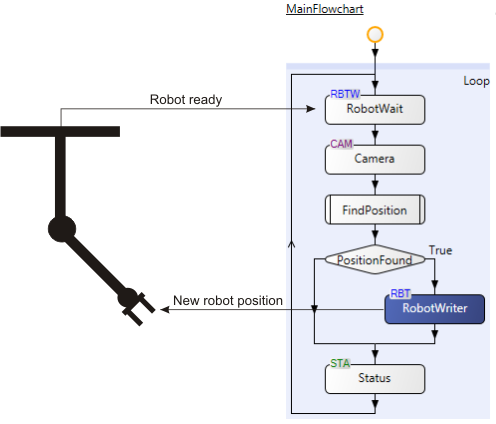
Using a robot controller with Matrox Design Assistant would
typically have a flowchart with a RobotWait step
near or at the top of the main flowchart loop, usually above a
Camera step. The RobotWait step
would pause the flowchart until it receives a request from the
robot controller. Program control will then return to the
flowchart, which would typically grab an image, process it, locate
an object or otherwise determine a position for the robot to move
to, and then send that position back to the robot controller
through a RobotWriter
step. The loop would then complete and return to the top, where the
RobotWait step
will pause until it receives the next request from the robot
controller.
The following flowchart demonstrates the general use case, with
the FindPosition subflowchart being all the steps that process the
image to locate where the robot should move to.
Position data is sent using the following 6 values: X, Y, Z, Pitch, Roll, and Yaw. In addition, for more
advanced applications involving multiple object/part types or
applications where multiple occurrences of objects might be present
in the field of view, you can use the ObjectId value to inform the
robot controller. For more advanced applications requiring
transferring data between a robot controller and Matrox Design
Assistant, you can use the Opcode value to inform the
robot controller about different operations.
Alternative
uses for the 8 values of the RobotWriter and RobotParameters
steps
The RobotWriter
step and RobotParameters
step send data to and receive data from the robot controller,
respectively. The data they transmit are named in Matrox Design
Assistant as the following 8 values: X, Y, Z, Pitch, Roll, Yaw, Opcode, and ObjectId. These values are
typically used to send position data, but can be repurposed. If you
use these values for an alternative purpose, you must ensure that
your robot controller code is modified accordingly.
Orientation
conventions
If you require changing a project to a different type of robot
controller, note that the rotation axis name (roll, pitch, and yaw)
represents different rotations about positional axes, and are
represented differently on the robot controllers of various robot
manufacturers.
|
Robot controller brand
|
Convention
|
Rotation axis name
|
|
Roll
|
Pitch
|
Yaw
|
|
Fanuc
|
Rotation about positional axis
|
Z-axis
|
Y-axis
|
X-axis
|
|
Robot notation
|
R
|
P
|
W
|
|
ABB
|
Rotation about positional axis
|
Z-axis
|
Y-axis
|
X-axis
|
|
Robot notation
|
The orientation is converted by the robot controller to a
quaternion.
|
|
Epson
|
Rotation about positional axis
|
X-axis
|
Y-axis
|
Z-axis
|
|
Robot notation
|
W
|
V
|
U
|
|
KUKA
|
Rotation about positional axis
|
X-axis
|
Y-axis
|
Z-axis
|
|
Robot notation
|
C
|
B
|
A
|
 Previous