Copyright© 2007-2019 by Matrox Electronic Systems Ltd. All rights reserved.
Contents
Wenglor weCat3D with Matrox Design Assistant
Network Interface Requirements
Creating the Design Assistant Project
Revision: Updated July 9, 2019 – added DCF file information
Wenglor weCat3D with Matrox Design Assistant
This document will guide you through setting up to capture depth map images from your Wenglor weCat3D into Matrox Design Assistant.
Overview
Matrox Design Assistant third party component for the Wenglor weCat3D uses the weCat3D GigE Vision interface. This software uses two network interfaces (NICs): one inputs from the physical camera and the other outputs images in a GigE Vision compliant manner. See network interface requirements section below.
Important note: Even though the Wenglor WeCat3D presents a GigEvision/Genicam interface, in this version of Design Assistant we do not treat it like a standard GigE camera. You must add it as a Third Party 3D device to receive depth map information.
General procedure
a) Connect the Profile Sensor/camera to a network adapter – by default it is at static IP address 192.168.100.1
b) Connect to the home web page of the camera. Note – it may not display well in all browsers (we had some difficulties in Chrome and IE11)
c) You can download the Operating Instructions using the Download link on the General device tab of the cameras web page. Configure the appropriate scanning parameters through the web page.
d) Download the GigE Vision server and its documentation from https://www.wenglor.com/fileadmin/download/SOFTWARE/GigE_SDK_Windows_X32_weCat3D_1.1.1.zip. Unzip and take note of the path to weCat3DGigEInterface.exe
e) Set up the GigEServer
i. Assuming you already have established connection to the weCat3D sensor for the previous steps.
ii. Configure the network adapter that the server will use to output GigE data – disable any other GigE Filter drivers that are associated with that NIC (Section 5 in the GigEVision_Interface_Description_EN.pdf)
iii.
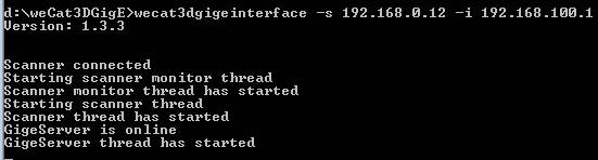
Using command prompt, start the GigE server with this command line
(Section 6 in the GigEVision_Interface_Description_EN.pdf)
weCat3DGigEInterface.exe -s SERVER_IP -i
CAMERA_IP
where
SERVER_IP is the IP address of
the server output network adapter and where
CAMERA_IP is the IP address of
the camera (weCat3d scanner)
iv. If you want the GigE server to start automatically when the PC is booted, you will have to add the appropriate command to your Startup
f) On a PC platform running Design Assistant X (either the same PC as the server, or another one)
I. Open Capture Assistant – it should discover the Wenglor GigE device.
II. Use the Feature Browser to adjust settings like exposure, number of lines, line trigger etc. (note: see section below on DCF files to use the new settings when the Design Assistant project starts up and allocates the device.)
III. Remember to Free the device in Capture Assistant before opening it in other applications.
Network Interface Requirements
Matrox Design Assistant third party 3D camera component expects to communicate via the weCat3D GigE Vision interface (aka GigE server). This means that three physical network adapters (NICs) are required:
- One NIC for the camera (GigE Vision interface input)
- One NIC for the GigE Vision interface output (this one must not be running any other GigE drivers)
- One NIC for MIL/DA input
· The camera and server must use different network interfaces (NICs). The server's IP address cannot be localhost
· All NICs will be handling high throughput and should be configured with jumbo packets/frames, max transmit buffers, and interrupt moderation turned on with interrupt moderation rate set to extreme. These settings are described in Matrox Capture Assistant help as well as in the weCat3D documentation
GigE Vision server setup examples:
1. Two PCs: The camera is connected to a PC running the GigE Vision server. Another PC running Design Assistant is connected to the connector that is the Output of the GigE Vision server. This can be a direct cable or a switch into which both PCs are connected.
2. Single PC: The camera is connected to a PC with three available NICs (such as a Matrox 4Sight GPm) running the server and DA with two network ports connected together.
Triggering
Design Assistant software triggers are supported, so the weCat3D can be triggered from the PLC using QuickComm, or via a button in the interface, or a Trigger flowchart step.
Design Assistant hardware triggers are supported as well. To configure for a hardware trigger:
1. In the camera’s web interface, click on the E/A settings tab. In E/A 3, set Pin function to User Input and Input load to on.
2. In Capture Assistant, open the Wenglor camera's feature browser and set the following value: Acquisition Control → Trigger Selector : FrameStart → Trigger Mode : On
Creating the Design Assistant Project
Open Design Assistant. Create a new project, and specify the WenglorWecat3D camera type.
Connecting to the weCat3D
Open the Platform Configuration dialog for PhysicalCamera1. Choose an allocation mode, enter the appropriate value for that mode and click Allocate.
Configuring the Camera step
In the Camera step, verify that the Camera Source input is PhysicalCamera1.
Setting Remap parameters
If your depth map image shows a range of colors from red to blue over your objects of interest, then the default mapping is suitable for your scan. However, if the original grabbed depth map shows mostly a small range of colors then on the Camera step Depth map Remap tab you may want to adjust the sliders to represent the actual range of distances your object occupies.
Setting Fill Gap parameters
Invalid pixels appear gray in Design Assistant depth maps when using a colormap. You can however replace some of the invalid pixel values with depths interpolated from neighboring pixels. You can choose to interpolate based on the size of the gaps, and on the height difference either side of the gap.
Using QuickComm
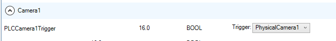
The Software trigger can be provided by the PLC directly using the Quick Comm PLCCamera1Trigger bit if you set the trigger target in the Platform Configuration page for EtherNet/IP or PROFINET.
Limitations
It is not treated like a GigE camera in this version of DA, hence CameraSettings step Edit GeniCam Features does not apply.
The wenglor GigE server does not save or remember its settings when power cycled. Genicam features can be adjusted using Capture Assistant, or Intellicam. If you want to make the edited values to apply at every DA project initialization, they must be stored into the digitizer configuration file as described below.
MIL limitation - only a single application can allocate a device at a time – when switching among Capture Assistant, Design Assistant, and Intellicam you must manually Free the device in one before Allocating it in another. For a deployed runtime project to be able to use the device, it must not be allocated in any other application.
Creating and using DCF files
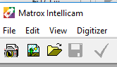
- Start Matrox Intellicam from the MIL Control Center, General Tools section
-
![]() Click New DCF toolbar button and Select GigEVision
format.
Click New DCF toolbar button and Select GigEVision
format.
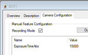
- From the Drop list on the Overview tab, select your device (must not be allocated in other applications)
- On the Camera Configuration tab, select Recording mode
-
Click Feature Browser toolbar button ![]()
- Make changes to the parameters you want to initialize so that they are added to the recorded list
-
- Save the DCF with a meaningful name
- You may examine the dcf text file in a text editor – make sure all the settings you need to initialize are there (mandatory – PixelFormat and FrameStart trigger mode.
- This version of DA uses a single dcf file – WenglorweCat3D.dcf - backup the original, if multiple configurations have been saved, you need to copy and rename the desired file.
-
Wenglor DCF file path
Assuming ProgramData is located on the C: drive: C:\ProgramData\Matrox Design Assistant\6.0\ThirdPartyCameras\Wenglor\GigEVision\WenglorweCat3D.dcf
Some settings have mandatory values:
- PixelFormat: "Mono16"
- ExtraData: "0"
- Scan3DRectified: "1"
- AcquisitionMode: "Continuous"
- TriggerSelection: "FrameStart"
- TriggerMode: "On"
Note that ExtraData and AcquisitionMode are already set to the above values when the GigE server is started.