Upgrading Projects from Design Assistant 4.0 to 5.x
October 23, 2017
Copyright© 2007-2017 by Matrox Electronic Systems Ltd. All rights reserved.
Having DA4 and DA5 on the same computer
Upgrading Projects from 4 to 5
Uses EtherNet/IP communication
EtherNet/IP and Profinet Field Definition
Non-default Publishing Update Points
Bug fixes requiring changes to project
Upgrading from IrisGT to IrisGTR
Getting started – Out of the box
Having DA4 and DA5 on the same computer
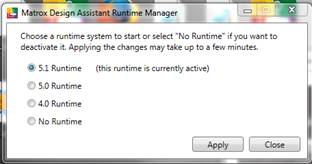
It is possible to install DA 5.0 and/or DA 5.1 on a computer that has DA4, as long as the computer meets the minimum requirements – in particular DA5 only runs on 64 bit systems. You can only run one version of the DA runtime environment at a time. Use the most recent RuntimeManager application to select which one is active. The utility is found in the DA 5 Tools folder, which is linked to from the MIL Control Center desktop icon.
![]()
Upgrading Projects from 4 to 5
Make a backup of the entire project folder before upgrading a project.
Most required changes are done automatically during the upgrade.
Any Custom steps must be rebuilt with the DA 5 references. DA 5 requires .Net framework 4.6.2 and so Visual Studio 2013 and 2015 are supported by the Custom Step Wizard. To create a custom step that runs on the Matrox IrisGTR running the Matrox Imaging Operating System requires Visual Studio 2017 which provides support for .NETCore and remote debugging.
Changes requiring Action
Pay particular attention if your project uses Ethernet/IP or Modbus communication. Some important settings have been moved out of the Setup step and must be entered into the Milconfig application. Milconfig is accessible from the MILControlCenter icon on the desktop. Make sure to run Milconfig on your target platform if you are not connected local host. This may require RemoteDesktop or a VNC client to access the target platform’s desktop if it does not have its own screen and keyboard.
Uses EtherNet/IP communication
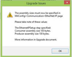
– the EthernetIPSetup step will be removed and you must use Milconfig to configure your EtherNet/IP settings and enable the protocol.
- If you must use assembly Ids different from 110 and 111 please contact technical support.
- during the upgrade you will be shown the number of bytes assigned to each assembly in the original project. Write these down, you will need to enter them in the Milconfig page
Uses MODBUS communication
– the ModbusSetup step will be removed and you must use Milconfig to configure your Modbus settings and enable the protocol.
If you don’t remember to enable modbus, the project won’t start – the operator view just sits waiting
EtherNet/IP and Profinet Field Definition
The fields (tags) of the input and output tables for Ethernet/IP and Profinet are defined centrally in the Platform Configuration dialog, rather than being spread out and duplicated in multiple Reader and Writer steps.
During upgrade, all the fields defined in reader and writer steps are collected centrally. The Readers no longer have any options, and the Writers show all the possible fields, with checkboxes to select the ones whose values will be changed.
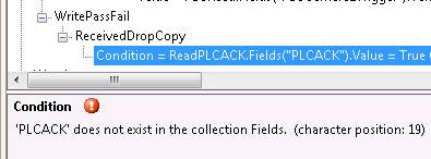
IMPORTANT – If your DA4 project uses any field names that conflict with the DA5 predefined Quick Comm field names, the upgraded project’s field will be renamed with a _DA4 suffix in the DataFromPLC or DataToPLC tables. However links to the fields will not be modified, so you will see which fields are affected in the Errors pane.
Rename the fields in the erroneous links, for example by adding the suffix _DA4
For example:
![]()
Multiple Camera steps
– the upgrade will attempt to determine an InspectionStart and an InspectionEnd point. In a simple project, the beginning of the main inspection loop is when a new image is grabbed. If you have multiple Camera steps it may select the wrong one as the start.
Other changes
The following changes should be transparent, but may cause small differences in the result values or behaviours of these steps in borderline cases
Default Image Queue
– the default image queue for triggered acquisition has been reduced from 10 to 4. This was done knowing that most applications running in steady state do not require more than one buffer to handle a trigger that comes in before the current processing is finished. Immediately after a project starts, there are some overheads of loading code into memory, setting up communication to the operator view, etc – so it is good to have some buffering if triggers will be arriving immediately on startup. With the use of more very high resolution cameras, especially in color, the amount of DMA memory needed to pre-allocate the previous default number of buffers (10) would exceed the default 64Mbytes of DMA, and the recommendation was to reduce the number of images in the queue anyway.
SubFlowcharts
All flowcharts found on the Project Flowcharts page are loaded, whether or not they are called. If you have obsolete flowcharts associated with the project, possibly from earlier or alternate versions, when they are loaded they may cause errors to appear. Use the Manage Flowcharts dialog to remove any unused flowcharts.
Non-default Publishing Update Points
If one of your Operator View Publishing Groups has publishing update points on Variable changed or other unusual update points. In DA 5 the moments at which publishing updates happen are now marked in the flowchart with circular markers on the step (as long as it is not a compound step, e.g. Condition.) You can also verify in the Synchronize Publishing dialog.
Blob
To speed up blob on small regions within large images, as of DA 5 the Blob threshold is applied only to the region (if there is one) rather than thresholding the whole image. This may change the value that is selected for Automatic thresholds – Bimodal, Lower and Upper.
CodeReader
- There is a new property InitializationMode that has the possible values ImprovedRecognition and TypicalRecognition to echo the addition in the underlying MIL library.
Upgraded projects have the Mode set to TypicalRecognition and retain the settings it used in DA4.
Newly created projects set the mode to ImprovedRecognition
It is not recommended to switch this input arbitrarily since changing it will clear many other settings. Hence it is visible only in the Property grid.
Reset points
In DA4 projects, the reset behaviour for analysis steps was NeverReset - and they will upgrade with that setting. However new steps added to the project between InspectionStart and InspectionEnd will have the new behaviour, Reset at InspectionStart. You can see the ResetPoint in the property grid.
Bug fixes requiring changes to project
Measurement Circle Marker,
In DA4, Constraint Radius values were not using calibrated values if the image was calibrated. In DA4 it was necessary to use TRANSFORMCOORDINATES to produce a pixel value if you were linking to a dimension result elsewhere in the project. In DA5 the inputs will behave consistently with all other DA inputs – positions and dimensions are in calibrated units. Remove any TRANSFORMCOORDINATE calls you may have inserted.
Upgrading from IrisGT to IrisGTR
Getting started – Out of the box
Unpacking and physical setup
Connect the three M connectors. If using the Breakout board in the starter kit, connect the pigtails (open end) of the Power/IO cable to connector J1 following the colour guide. If not using the breakout board see Append in the Iris GTR.pdf Installation Guide
- The Network cable and the PowerIO cable for the GTR are different from the IrisGT cables.
- The starter kit breakout board is different from the IrisGT
- The VGA/USB cable is the same
Initial Bring-up and Grab
Refer to the Getting Started with Matrox Iris GTR and Design Assistant 5.x document found in the Documentation folder and as an Appendix in the User Guide.
The Portal Pages
have been updated.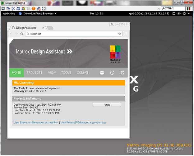
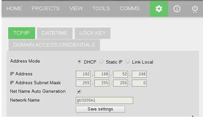
Network settings
- the IrisGTR is shipped from the factory in DHCP mode.
- The IrisBootParams utility has been replaced by the IrisGTRDiscovery utility, available in the Tools folder via MIL Control Center.
-
The network settings can also be changed from the Design Assistant
Settings ![]() portal page, or through the operating
system’s settings.
portal page, or through the operating
system’s settings.
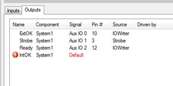
– the Iris GTR only has 3 auxiliary output pins. If your IrisGT project used 4, you will see the following error.
- the operating system has changed from WindowsCE to the Matrox Imaging Operating System (MIOS) which is a Linux based system.
- The IrisGT UserDisk partition does not exist in the GTR. On the GTR the main folder is the user folder mtxuser. Its subfolder “Documents” contains the default folders used by the ImageWriter and TextWriter flowchart steps. The second important subfolder for backup purposes is “da” which resembles the IrisGT’s UserDisk – in that it holds all files pertaining to deployed projects, calibrations, recipes and persistence. Accessing the fileshare from another system requires authentication with username mtxuser and password Matrox.
- The IrisGT RAMFiles partition does not exist in the GTR.
- Some administrative settings that used to be found in the IrisGT Portal Pages are now found in the Milconfig application, which is accessible from the desktop display of the IrisGTR. These include Licensing, enabling the Profiler, and enabling Profinet (as well as Ethernet/IP and Modbus).
- Other links in the IrisGT portal pages for listing files and processes and Telnet utilities have been replaced with Console commands.
- UserLED step has been removed.
- MulticamHMIViewer – has been removed, the corresponding OperatorView page has been removed and the View application has been removed.