Copyright© 2007-2019 by Matrox Electronic Systems Ltd. All rights reserved.
Contents
LMI Gocator with Matrox Design Assistant
Creating the Design Assistant Project
LMI Gocator with Matrox Design Assistant
This document will guide you through setting up to capture depth map images from your LMI Gocator into Matrox Design Assistant. Gocator line profilers and snapshot sensors use the same approach.
Design Assistant software triggers are not supported. The Gocator must be configured to Surface mode, and to trigger based on external signals or part detection via the Gocator web interface before Design Assistant can acquire depth maps from it.
Installing the Gocator SDK
· The Gocator SDK folder must be installed on the target platform. Version 5.1 can be found at https://downloads.lmi3d.com. The user must have an account with LMI to access it.
o Currently we require Version 5.1 (Not 5.1 SR1, 5.2, etc).
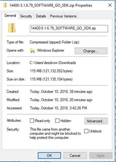
o The download contains DLLs. Some systems will automatically block downloaded dlls from loading as part of their security.
o After downloading the SDK zip and before uncompressing, verify its properties and check Unblock if it is offered as below
![]()
· The SDK is just a folder which can be copied anywhere on the PC. Using Control Panel, System, the user must create a system environment variable named LMI_GO_SDK_PATH with a value that is the path to the SDK's folder. Otherwise, Design Assistant will not know where the SDK is located. A reboot is needed.
Running the Gocator web app
· Before creating a project in Design Assistant, the user should tune the camera's settings in the web interface, which is accessible in an up to date web browser with the camera's IP address. Adobe Flash is required.
o The camera's default IP address is 192.168.1.10 (static). In this mode, the PC's network adapter must have its IP set to a different address in the same subnet, for example 192.168.1.5 and its subnet mask set to 255.255.255.0. This is explained in the QuickStart Guide, for example https://downloads.lmi3d.com/gocator-2100-2300-series-quickstart-guide.
o If the camera is connected to a network switch, its IP address has to be changed manually or enable DHCP via the web interface or network discovery tool (separate application).
o The camera cannot be behind a router for SDK to camera communication: https://support.lmi3d.com/kb_article.php?ref=3803-TSGK-4215
o ***Take note of the serial number/ID on the sticker or the IP address of the device, you will need them in the Design Assistant project
· Set up the scanning parameters
o Set up your camera respecting the scanning zones described in the datasheet for your Gocator model.
o Perform an alignment to align the horizontal with a flat reference surface.
o Adjust exposure as appropriate for your objects ( differs for black or white)
o Set the scanning speed or encoder parameters so that the fixed length scan acquires your entire object. Alternately, if using the part detect mode set the parameters for recognizing that an object is in the field of view.
o Verify that the output images are as expected.
Creating the Design Assistant Project
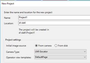
Create a new project and select LMIGocator from the list of supported camera types.
Connecting to the LMI Gocator
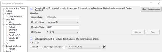
Open the Platform Configuration dialog page for PhysicalCamera1.
Choose an allocation mode, enter the appropriate value for the mode and click Allocate. Status should change to Allocated.
Configuring the Camera step
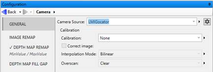
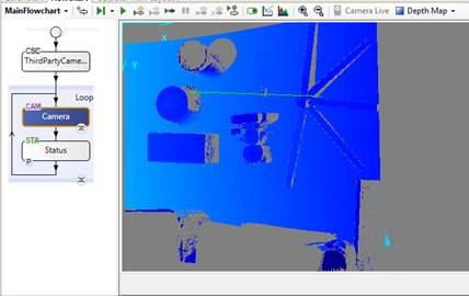
Select the Camera step.
The Gocator does not accept Design Assistant software triggers. When you run the Camera step in Design Time, it will show “Waiting for Camera execution” in the Wait notification bar until the Gocator has been triggered by an external trigger or a part detection, depending on the way it is configured.
Setting Remap parameters
If your depth map image shows a range of colors from Red to Blue over your objects of interest, then the default mapping is suitable for your scan.
However, if the original grabbed depth map shows mostly a small range, you can select the Depth Map Remap tab and adjust the sliders or choose a Start/End Mode specifying 3 standard deviations either side of the mean to select a smaller range of Z values to focus on.
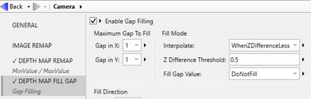
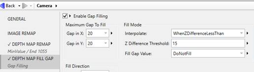
Setting Fill Gap parameters
Invalid pixels appear gray in Design Assistant depth maps when using a colormap. They appear black in the Gocator web interface.
In Design Assistant, you can replace some of the invalid pixel values with depths interpolated from neighboring pixels. Generally, this is done over small gaps (small in XY extent and small in Z difference). In this example, only single pixel wide gaps are filled.
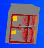
The line profile graph shows the invalid pixel locations in red. You can use the vertical markers on the graph to measure the width of the gaps and evaluate the Z difference.
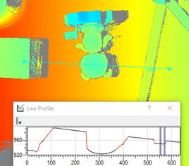
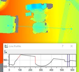
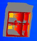
In this example, limiting the width of gaps to fill to 20 pixels and the Z difference to 15 we see the edges around the ruler have been replaced, but the large shadows have not.
Limitations
- If the Gocator is being triggered more often than the Design Assistant project is consuming the images, the internal queue may fill up. When the DA camera step runs in the future it will be fetching stale queued images. To clear the queue in Design Time, in the Platform Configuration dialog PhysicalCamera1 page click the Free button, then click the Allocate button.
- If you have both the Gocator web interface and Design Assistant design time open and connected to the Gocator, if you turn off the laser (stop scanning) in the web interface, DA will not turn it on unless the sensor is freed and reallocated.