Introduction to Matrox Design Assistant X
March 20, 2019
Copyright© 2007-2019 by Matrox Electronic Systems Ltd. All rights reserved.
Table of Contents
Introduction to Matrox Design Assistant X Version 190X
Communication Protocols on the Iris GTR
Third-party 3D sensor supports depth maps
Getting Started with Multiple Runtimes
Running template and example projects
Introduction to Matrox Design Assistant X Version 190X
This document presents some new concepts and discusses some of the major differences in Matrox Design Assistant X compared to previous versions. There is some overlap in the information presented here, in the readme, and in the User Guide.
Platform
Matrox Design Assistant consists of a design-time application with which you build, configure and test project flowcharts, and a runtime environment in which one or more deployed projects can run independently of the design-time applications. We refer to the runtime system’s hardware plus software as the target runtime platform, or “platform” for short.
Multiple Runtimes
New in DA X Version 190X: Support multiple runtime projects running simultaneously on PC platforms. For installations with multiple independent inspections, for example several cameras triggered at different rates, and each reporting their results independently.
o More than one DA project may run on a platform, as long as the projects have different names, and do not make conflicting resource requests (e.g. I/O pins)
o More than one project can be selected to start automatically on system boot
o Portal Pages have been restructured to accommodate multiple running projects.
Third Party 3D Sensors
New in DA X Version 190X: Support for Third Party Sensors in the Camera components group. Included with the installation are components for LMI Gocator and Photoneo Phoxi devices. Additional device support in development. Information on working with the resulting depth map images is found below.
Linking and Binding
New in DA X Version 190X: Platform components can be accessed through links. The link tree has a new tab, in addition to Inputs, Outputs and Variables there is a Platform group.
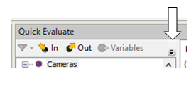
Note that, due to space constraints, often the Platform tab is not visible until you click on the extension button.
Links can be used to display the current value of platform settings, for example
Platform.Cameras("PhysicalCamera1").ExposureTime
New in DA X Version 190X: Operator View Input elements can be bound directly to inputs of platform components, simplifying the adjustment of ExposureTime.
Limitation – in this first implementation of platform binding, only those inputs which are present in the steps CameraSettings (excluding Edit GeniCam features), IOSettings, TimerSettings and Online/Offline for Quick Comm protocols are bindable.
Communication protocols
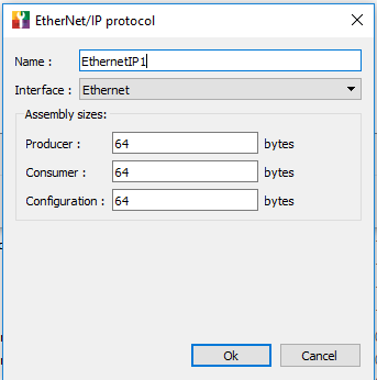
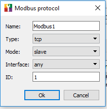
New in DA X Version 190X: Concept of Industrial Protocol Instances
- Each runtime maintains its own connection to an industrial protocol (EtherNet/IP, PROFINET, Modbus)
- Each independent connected channel is called an Instance
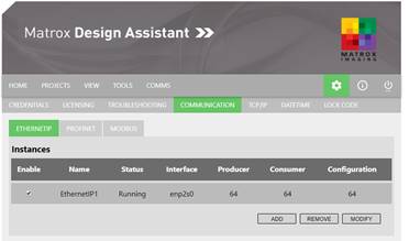
- Instances are created, configured and named using the Communication page of the MilConfig utility running on the target runtime platform.
o By default, an instance has been created for each protocol, but is not enabled. For single runtime, as in the previous version of DA, you just need to check Enabled and make sure the parameters correspond to what the PLC is using
o Each instance has an “Interface” setting which indicates the physical network interface (NIC) or a virtual network interface on which to communicate
o Use the Add button to create additional instances.
§ Multiple Instances can be created with the same Interface NIC, but only one can be started at a time.
§ If you do not have sufficient physical NICs in your system, it is possible on Windows 10 systems to create Virtual NICs. Information can be found in Converged Fabric in Windows Server 2012 Hyper-v (https://blogs.technet.microsoft.com/meamcs/2012/05/06/converged-fabric-in-windows-server-2012-hyper-v/)
§
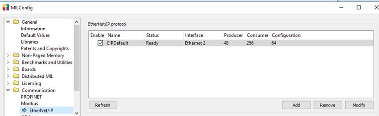
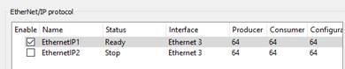
o Example of configurable settings
-
-
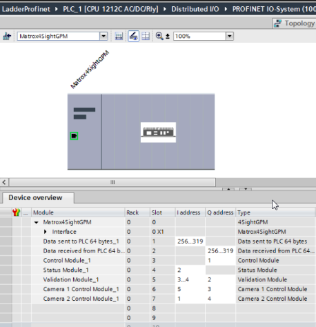
Changed in DA X Version 190X: PROFINET –
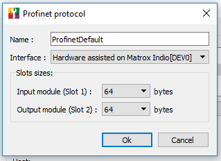
- only supported on platforms with hardware assisted PROFINET – IrisGTR, 4Sight GPm, Indio, etc.. Software only mode has been discontinued (not certifiable)
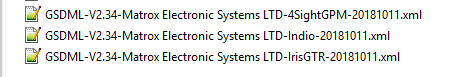
- New GSDs: One per platform. The GSD files are provided in C:\Program Files\Matrox Imaging\MIL\Config\Profinet.
- In the new GSDs, CameraControl modules start at Slot 6 instead of Slot 7. NOTE – if you switch between DA 5.1 and DA X runtimes on the same PC platform, you must install DA 5.1 Update 7 to provide backward compatibility once MIL Update 68 has been installed on your PC.
- Additional CameraControl modules can be added from the Catalog Pane.
- Refresher: to support Quick Comm with PROFINET, multiple modules are used for the Matrox vision device. The Data modules are accessible via the ProfinetReader and ProfinetWriter steps. The Control, Status, Validation and Camera modules are reserved for QuickComm.
-
Communication Protocols on the Iris GTR
To simplify the configuration of Iris GTR, the communication pages of MILConfig are echoed in the GTR’s configuration portal, allowing you to set it up as long as you have browser access to the camera. In previous versions of Design Assistant it was necessary to access the GTR’s desktop (e.g. via VNC) to run Milconfig.
Processing
New steps:
- CircleFinder, EllipseFinder, RectangleFInder and SegmentFinder
Available if you have the ModelFinder license.
- PhotometricStereo
Using 4 images acquired with varying directional lighting, produces registered combined images that highlight surface roughness.
Typically used with quadrant aware lighting controllers such as offered by SmartVision (SVL) and CCS.
New Photometricstereo example works with images or live grab.
- CNNClassIndex
Loads a CNN deep learning context that has previously been trained.
- CodeGrade
Replaces the previous CodeVerify custom step.
- The Add step dialog has been reorganized by functional groups.
Processing changes:
- Modelfinder runtime reconfiguration of DXF models
- ModelFinder and PatternMatch – added editable annotation for ReferencePoint reconfiguration. Added ModelFinder edgel annotations (model and target) to Operator View and ImageWriter.
- ImageProcessing threshold and window levelling panes use new sliders, improved initial values, support for Z scale calibration
Workspace
Project changes:
- New project dialog offers choice of camera type, including supported third party 3D sensors (see below)
Image Object changes:
- High bit depth intensity images (e.g. 16 bit images from thermographic cameras) now automatically display using the Autoscale mode.
- Additional colormaps, independent colormap per images for steps with multiple output images
- Image outputs now include images statistics (min, max, mean, etc.) and pixel calibration factors (x,y,z if applicable)
- The camera step provides optional data remapping to 8 or 16 bit depths to feed appropriate images to analysis steps
Recipes
- Recipe handling has been greatly optimised in design time. Only the current recipe is loaded when the project is loaded, improving project load time.
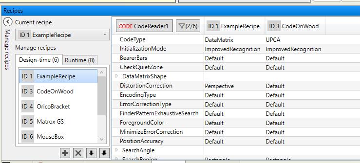
- The Recipes pane has a new layout.
- due to the importance of synchronizing your design time project with any changes or additions that were applied in runtime, the Manage recipes section is displayed by default
- comparison between recipes is done per step, and the filter (funnel) button lets you select which recipes to compare
- the Apply multiple option allows you to quickly make a modification to several recipes at a time (even if they are not currently loaded in the comparison table)
- Only variables that are “persist per recipe” appear in the recipe pane. Globally persistent variables are only shown in the Manage Variables dialog.
Portal Pages
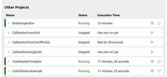
- Main portal page redesigned in tabular form.
o The triangle and square buttons are used to run or stop individual projects. The rightmost icons opens the Operator View of the project.
o The top section shows all projects tagged to start automatically after reboot.
o The next section shows all other deployed projects
-
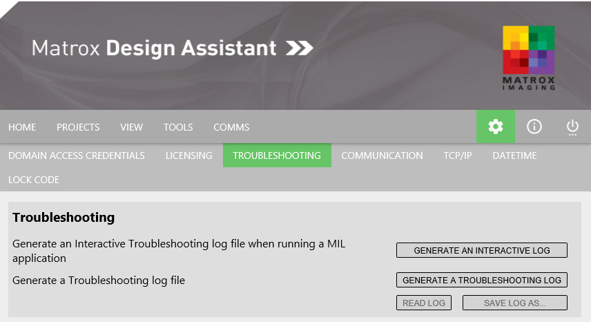
IRIS GTR
o Additional settings pages: Licensing, Troubleshooting and Communications provide the same settings as the corresponding MILConfig pages. The major advantage is that you can now access them simply through the portal, rather than having to connect to the IrisiGTR’s desktop via VNC or a physical keyboard/monitor.
o
OperatorView
New in DA X Version 190X: The Operator View Display element supports colormaps and display modes such as Autoscale for high bit depth images
New in DA X Version 190X: Input elements can be bound directly to inputs of platform components. Previously an input could be bound only to a step input or variable of the flowchart.
- Added direct binding of Operator Input elements and links to platform component inputs (for example camera exposure).
The bound values can be persistent per recipe or globally. No longer need to call CameraSettings, CommSettings, IOSettings and TimerSettings steps at initialization and recipe change.
- Step inputs that are bound to the operator view have a “B” tag next to them in the step configuration pane
New in DA X Version 190X: Added multi-language support, sometimes called localization. The developer creates a separate file for each language. The Portal Page displays a drop list to select the current language. Documentation and sample available in the Quick Start Tutorials page.
New in DA X Version 190X: Added an editable annotation for interactively reconfiguring model reference points. See also the Processing section.
Third-party 3D sensor supports depth maps
- Added platform interface Camera components for Photoneo PhoXi 3D camera and LMI Gocator line profilers.
· The third party 3D sensor interface acquires the output data from the 3D sensor’s API/SDK including range, intensity and confidence components and makes the data available to the camera step.
· Setup and configuration of the device is done using the manufacturer’s interface software.
· In the Documentation folder, added setup guides: Photoneo PhoXi with Matrox Design Assistant.pdf and LMI GoCator with Matrox Design Assistant.pdf
- Camera step:
· CameraSource parameter accepts the name of installed third party 3D sensors.
· Support for depthmap images with new tabs.
· Gap filling methods for invalid data points.
· Generation of 8 and 16 bit integer remapped images allowing other DA steps to process depth map images.
- ImageWriter step:
· Option to save all the components of a depth map, or to save individual components.
· Image Sets automatically recognize depth map data sets.
· Project Change Validation records and verifies depth map data sets.
- Display view
· Depth map images produced by 3D sensors are generally 16 or 32 bits deep, and are best viewed with a color map. A “Jet” multi-hued color map is used by default for depth map images. Using the right mouse menu in the display, other colormaps may be selected.
- Calibration
· Range images produced by 3D sensors are typically in real world units (for example millimeters). The calibrated depth information (i.e., Z) is respected by Design Assistant.
· Step inputs that are usually in intensity units (e.g. threshold levels) are entered in Z world units when operating on a depth map.
· Cursor coordinates, line profiles and histograms report Z values.
· A function TRANSFORMZ is provided for situations where a conversion between world coordinates and image pixel values is required.
Template projects
- Modified to use platform binding – exposure setting is more responsive
- Incorporate an Online-Offline toggle. Training and configuration can only by done when Offline. If you have enabled PLC Quick Comm for the template, the PLC should monitor the Online bit (bit 0:7) and refrain from sending triggers while the project is not online.
Customs steps
The provided custom step examples use WPF.
Custom Step Wizard for Visual Studio 2017 (.NET Standard)
Getting Started with Multiple Runtimes
Camera allocation
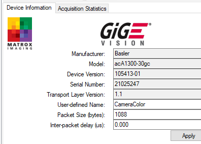
To run simultaneously more than one project that grabs from physical camera, it is essential to set the camera Allocation Mode to select a particular camera. In the Platform Configuration dialog you can choose either IP address or the user defined Camera Name stored on the camera.
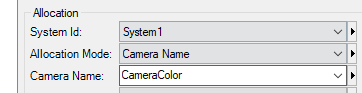
The user-defined name can be applied using the Capture Assistant utility.
Running template and example projects
The projects loaded from the Start Page use a default allocation mode that is suitable for single runtimes. If you want to run simultaneously multiple templates, utilities or examples that grab you must change the camera allocation mode as described above before deploying the projects.
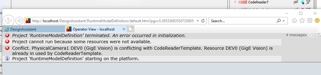
Troubleshooting
If you do not modify the project to use a specific camera, and you start two projects with the default allocation mode (Device Number) you will get the following sort of message when the second one starts.