Introduction to Matrox Design Assistant 5.0
May 4, 2017
Copyright© 2007-2017 by Matrox Electronic Systems Ltd. All rights reserved.
Table of Contents
Introduction to Matrox Design Assistant 5.0
Variables, Expressions and Store step
Introduction to Matrox Design Assistant 5.0
This document presents some new concepts and discusses some of the major differences in Matrox Design Assistant 5.0 compared to previous versions. There is some overlap in the information presented here, in the readme, and in the User Guide.
Platform
Matrox Design Assistant consists of a design-time application with which you build, configure and test project flowcharts, and a runtime environment in which a deployed project can run independently of the design-time applications. We refer to the runtime system’s hardware plus software as the target runtime platform, or “platform” for short.
New in DA 5.0: Support for the Matrox Iris GTR smart camera platform. The previous generation Matrox Iris GT smart camera is supported in DA version 4.0.
New in DA 5.0: CameraFocus step which is compatible with the VariOptic liquid lens that can be plugged into the IrisGTR. The CameraFocus provides autofocus modes if you have the supported lens, but can also provide a measure of sharpness when using a regular lens.
Coming to DA 5.0: Support for the Matrox Indio board which provides encoder input and hardware timer output via the Matrox IO Engine, as well as hardware assisted Profinet.
Changed in DA 5.0: Only 64-bit Windows operating systems are supported for the DA Development package.
Workspace
New in DA 5.0: Expanded Project Toolbar includes a droplist of all subflowcharts and buttons for TryIt/Debug items. The Action pane is now collapsed by default.
![]()
New Platform Toolbar gives direct access to Platform Configuration, Deploy, Communication and Pending Action items.
![]()
New in DA 5.0: The Start Page has been totally re-organized.
New in DA 5.0: Images are displayed with an initial zoom factor so they appear within the display. The mouse wheel lets you zoom in and out quickly around the position of the cursor.
New in DA 5.0: New category of Template projects has been added. These projects are ready to run for codereader, presence/absence and SureDotOCR applications. They support configuring the necessary regions and settings at runtime, as well as the creation and modification of recipes.
New in DA 5.0: Multiple copies of the DA design time program can run at the same time. Only one can connect to a particular platform at a given time, but multiple instances can connect to different platforms or be in Emulation mode. Copy/paste between instances is supported.
Communication protocols
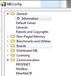
New in DA 5.0: EtherNet/IP, Profinet and Modbus communications must be enabled in the Milconfig utility before they can be used by a Design Assistant project. This is a side effect of the communication modules being made available to MIL developers as well as to DA users.
Additionally you must select the Profinet option for the runtime platform at installation; otherwise the necessary low-level components will not be installed.
Changed in DA 5.0 : The fields (tags) of the input and output tables for Ethernet/IP and Profinet are defined centrally in the Platform Configuration dialog, rather than being spread out and duplicated in multiple Reader and Writer steps.
New in DA 5.0: QuickComm - new predefined communication mapping, handshake sequence and event-driven camera triggering for EtherNet/IP and Profinet communications. New projects that select QuickComm will handle typical handshake, ProjectReady, Trigger, Busy, OverallPass, OverallFail without adding any steps to the flowchart.
When using QuickComm with Ethernet/IP the first 32 bytes of both the Producer and Consumer assemblies are reserved for QuickComm. The remainders of the assemblies are available for user-defined data accessed through the EthernetIPReader and EthernetIPWriter steps.
When using QuickComm with PROFINET multiple modules are used for the Matrox vision device. A GSD file with QuickComm compatible definitions is provided in C:\Program Files\Matrox Imaging\DA 5.0\Config\Profinet. The Data modules are accessible via the ProfinetReader and ProfinetWriter steps. The Control, Status, Validation and Camera modules are reserved for QuickComm.
If using Profinet without QuickComm, for example to be compatible with existing projects or control ladders, you can delete the QuickComm specific modules if you are short of memory.
Legacy projects will continue to work when upgraded to DA5, but will not take advantage of the new mechanisms.
Note that if you choose QuickComm the handshake will Wait for certain signals from the PLC before continuing the flowchart. If the PLC is not available it is very important to provide ways to set communications Offline.
New in DA 5.0: Some DataToPLC fields can be configured to automatically send their linked result values to the PLC at the InspectionEnd point, without having to add a Writer step. The QuickWatch windows have a right mouse menu item to identify results that will be automatically transferred.
New in DA 5.0: Communications Menu allows setting various components offline in design time.
New in DA 5.0 – steps to change platform settings at runtime – in addition to CameraSettings which has always been available, there are now CommSettings, IOSettings and TimerSettings. See the Operator View section for equivalent Button Actions. New expression function ISONLINE can determine the state of the industrial communication protocols.
Recipes
New in DA 5.0: DA 5 supports multiple product variations, called recipes. Steps of the flowchart that are recipe dependent are flagged with an R, and a separate configuration of each recipe step is stored with the recipe name. When the current recipe is changed, either on instruction from the PLC, or in response to an OperatorView request, all recipe steps are re-initialized with the appropriate settings, regions and models.
Recipes have both a name and an ID number. The name is more convenient for operator view selection, and the ID number is more convenient for PLC management of recipes.
Additional recipes can be created either in DA design time, or while the project is running from the Operator View. Recipes that were created at runtime can be imported back into the design environment for verification, modification or redeployment to other platforms.
New in DA 5.0: Project settings that are persistent (marked with a P) and were modified at runtime through the Operator View can be brought back into design time using the Synchronize operation. This allows them to keep the most recent values even if the project is redeployed.
New in DA 5.0: The template projects illustrate how to incorporate runtime recipe management into your own projects. There is a separate Start page for template projects.
New in DA 5.0: An “Append current recipe” option in Image Sets and the ImageWriter step support organizing images in a separate sub-folder per recipe. This is often used with the new PATH parameter “DA Project”, so that the images belonging to a project are in the same folder.
Flowchart behaviour
New in DA 5.0: AutoRun mode – not only are Preview annotations updated when you change a configuration setting, but also the result table is brought up to date. You may be prompted with a large green run button in the image display if the flowchart needs to be updated.
New in DA 5.0: Analysis result Callouts – small annotations associated with every result. Clicking on the Callout pops a QuickWatch window – displaying the most important values of the selected result.
A Filter option provides access to more detailed results in the QuickWatch.
The right mouse context menu in the Quick Watch lets you send result links to the DataToPLC table .
New in DA 5.0: Automatic creation of Links with Drag and Drop – Drag a result from a QuickWatch window and drop it on an Input box – the link will be created (without having to dig through the Link tree) This is a big timesaver particularly for Measurement, StringReader and ModelFinder steps which have a deep structure.
New in DA 5.0: InspectionStart and InspectionEnd action points indicate when QuickComm fields are set or reset, when OperatorView information is published, and when step results from the previous inspection loop are cleared. The default points are the end of the first Camera step and the bottom of the main loop.
New in DA 5.0: Reset result outputs – by default, analysis steps added between InspectionStart and InspectionEnd points will automatically clear their outputs when starting to inspect the next image (InspectionStart)
New in DA 5.0: Subflowcharts can be run in response to an Event. An event can be a change in an Operator view input element. An event can be a change in a specified incoming field in the QuickComm mapping. The subflowchart will be pending from the time the event occurs, until the end of the current inspection, so that the current inspection can compete correctly. If the event happens outside an inspection, for example while waiting for a trigger to acquire the next image, it will be handled immediately, and then the wait resumes.
In Design time you can force the execution of
an event-driven subflowchart with the following toolbar buttons
![]() .
.
New in DA 5.0: QuickRun mode – to isolate a step and any steps it depends on, hiding all others. This can be useful in a large flowchart if you want to focus on testing or tweaking a particular processing step, skipping all steps that are not contributing to the step selected as the “root” of the QuickRun group.
OperatorView
New in DA 5.0: DA web pages (Portal Configuration and Operator View) now use HTML5. They no longer use ActiveX technology. The pages can be viewed in HTML5 capable browsers, Firefox, Chrome, etc. There are limitations with Microsoft Edge.
New in DA 5.0: The configuration panes of all Operator View Input elements have been restructured into tabs. Tabs which are common to all input elements include Subflowchart to be executed on data changed, and binding to the flowchart.
New in DA 5.0: Input elements can be bound directly to the Input of a step of the flowchart. Previously an input could be bound only to a variable of the flowchart. Note: the target bound input in its configuration pane does not indicate that it is bound – it can only be seen in the Operator View element.
New in DA 5.0: Annotations in the Display of the Operator View - have an additional “Label” portion which can automatically display occurrence numbers, model names, or other information.
New in DA 5.0 – Button Actions to change platform settings at runtime – in addition to CameraSettings which has always been available, there are now CommSettings, IOSettings and TimerSettings.
New in DA 5.0 – Publishing Update points can be Conditional. For example, you can publish an image of the last failed part only when there is a Fail result in the Status step. This does not require adding any steps or variables to the flowchart.
Removed in DA 5.0 - -MulticamHMI – the MulticamHMIView OperatorView page has been removed and the Viewer application has been removed.
Projects with discrete I/O
A project that uses I/O can only be deployed on system platforms that provide supported I/O – for example Matrox Iris GTR smart cameras or Matrox 4-Sight systems or GigEVision and USB3Vision cameras that provide SFNC compliant DigitalIO features or systems containing a Matrox Indio card.
Furthermore, not all platforms have the same number of inputs and output. In particular the IrisGTR has one fewer outputs than the Iris GT.
New in DA 5.0: Platforms with latest version Matrox IO engines support synchronization of multiple camera grab queues, even if the conveyor is moving while the vision platform is restarted.
Processing
New in DA 5.0: SureDotOCR step specialized for reading characters printed with a dot matrix printer.
Changed in DA 5.0: The BlobAnalysis step configuration panes have been re-organized to make the accuracy of diameter measurements and enabling output image easier. Less often used options have been moved to and Advanced page.
Changed in DA 5.0: The Metrology step has been completely restructured. The toolbar offers only Constructed and Parametric features and Tolerances. Measured features are only accessible through the Configuration pane. Constructed features and Tolerances can be created by clicking on the result annotations from other steps – causing an automatic import of position or edge information from Blob, EdgeLocator or Measurement step results.
Changed in DA 5.0: The CodeReader step uses the new MIL improved recognition mode.
New in DA 5.0: Modelfinder accepts DXF files for model definition.
New in DA 5.0: Status step conditions can be conditionally enabled.
Other
New in DA 5.0: ImageWriter step supports writing to FTP (TBD and anonymous http:))
New in DA 5.0 Image Writer can scale the image to requested size before overlaying annotations. Allows producing small images for HMI displays of limited resolution.
New in DA 5.0 – use http to access image saved in a folder on the runtime platform, e.g. http://192.168.52.96/savedimages/HMIImage.jpg
New in DA 5.0: synchronized grab of multiple cameras using the Matrox Auxiliary IO Engine if available, even if conveyor is moving while the platform is initializing.
Variables, Expressions and Store step
Changed in DA 5.0: Variables are now “global”. They can be read or written by any flowchart or any bound OVInput element. Previously they could be read by all, but only written by the owner flowchart.
Changed in DA 5.0: The Store step has been redesigned to make it easier to work with large numbers of variables.
New in DA 5.0: Additional Expression functions – HOSTNAME, IPADDRESS, MACADDRESS allow you to display or log identification information of the runtime platform.
New in DA 5.0: Additional Expression functions – LISTFILES, FREESPACE, TOTALSPACE and a DeleteFiles step allow managing storage space on the platform.
Redesigned Portal Pages
Calibration and View utilities for multi-camera platforms allow you to select which camera you are working with
Project Change Validator
New in DA 5.0 – A framework for validating whether changes made to a project or its inputs have not changed the project output. Viewed another way, a regression test on a set of validation images confirms whether results are as expected, or whether new passes or fails have been introduced. Validation can be requested by the PLC when using QuickComm and from the Portal Pages dedicated to the Product Change Validator. A validation set comprises a set of images, data indicating the pass/fail of each of the Status conditions, and a copy of the DataToPLC and DataFromPLC maps.